Definition

A fire hydrant is a connection point where water is accumulated and connected by pumps by which firefighters can efficiently fight with fire.
Components & their Installation
a. Fire Water Reservoir: Tanks of adequate capacity depending upon the risk to be covered. They should be located between 60 to 200 meters from the risk. Proper approach roads of at least 3.6 meters width should be provided.
Arrangement should be made to divide these tanks in two compartments such that one compartment is always available for service while the other can be taken out for cleaning or maintenance purposes. [Static or Terrace tank for storing water for firefighting purpose]
b. Main Pumps: A minimum of two pumps one electric and other diesel driven (stand by) should be installed to provide water at a required pressure. It is preferable to make them start automatically once the pressure drops, below the minimum required. Both pumps can be electrically driven provided the source of power supply is from different sources. The capacity of the pump shall be according to the nature of Hazard.
c. Jockey Pump: A pump of 500 liters / minute capacity is installed for maintaining pressure in the network. As and when the pressure drops this pump starts automatically to raise the pressure to present pressure / cm3 and then stopping by itself. In case the pressure drops below the set pressure the main pump starts automatically.
d. Ring Mains: It is net pipe work laid underground. These can be laid above ground as per the feasibility provided the pipes are sufficiently supported for its stability, at least one support every 10 feet. These are laid in ring pattern along the side of the roads/passage:
- The hydrants are located between 2 to 15 meters from the building to be protected in non-hazardous areas and 30 meters from the edge of the building accommodating hazardous stores.
- The size of mains is decided such that desired pressure is available at the hydraulically remotest point.
- Material of construction of mains is normally cast iron as this is anti-corrosive and cheaper. However, if MS is to be used this must be coated with good quality of anticorrosion point and suitably wrapped.
- Hydrants are installed in such a way that risk is protected from two independent sources of water supply.
[rise mains, down-comer mains or external mains to feed water from the source to the required point under pressure]
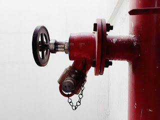
e. Single Hydrants: These are the points from where fire hoses are connected for drawing water. Single outlet is fixed with 63 mm diameter instantaneous female coupling with a wheel type control valve called the landing valve coupled to 80 mm diameter standpipe through a bend. It is erected 1 meter above the ground level.
f. Double Hydrants: In this case the stand post diameter is 100 mm provided with a ‘T’ at the top. To each end a landing valve is fixed.
g. Riser Mains: These are provided where the hydrants are provided on upper floors of the building. These have one main isolation valve at the ground level. The diameter of such mains is 150 mm reduced to 100 mm at the top.

Water tanks: A satisfactory supply of water for the purpose of firefighting shall always be available in the form of underground/terrace level static storage tank with capacity specified for each building with arrangements or replenishment. Tanks of adequate capacity depending upon the risk to be covered. These should be located between 60 to 200 meters from the risk.
· Underground static water tanks
· Surface water tank
· Terrace tank
· Riming tank
The underground fire water storage tank(s) shall not be more than 7 meters in depth from the level having fire brigade draw-out connection, while the draw-out connection shall not be more than 5 meters away from the tank wall. The covering slab shall be able to withstand a total vehicular load of 45 tons (or as applicable) equally divided as a four-point load when the slab forms a part of pathway / driveway.
Water Tank Requirements
- At least two manholes each of adequate size should be provided on the tanks (outside the pump house) so as to facilitate fire appliances to draw water from tank when necessary.
- Access road to the tank were located outside the building should be at least 6 meters in width and the same should be designed suitably to bear a load of fire appliances weighing up to 18 tones. The access road should be kept free from encroachment and obstructions at all times.
- The tank should not be more than 3.5 meter deep having a slope (1:100) and 1 meter sump of 1mX2m at the lowest end. The side with sump should preferably be at the front and should have an easily removable manhole cover through which fire engine suction hose can be lowered into the sump for direct pimping.
- Underground tanks should be provided with compartments with external interconnection at bottom levels having gate valves at both the ends for periodical maintenance / cleaning purpose.
Fire Pumps and Pump House
The pump house should be located preferably outside the building with a minimum clearance of 6 meter from adjoining buildings. The pump house should have adequate natural ventilation with windows, fitter with expanded metal for protection. If the pump house, houses a diesel pump, the exhaust pipe of the diesel engine should be extended to outside the pump house and exhaust discharged at an appropriate height in the open air.
The floor of the pump house should be sloped to the farthest end to drain away any water leaking from glands, valves, etc. The pump house should have normal lighting, and also emergency lighting facility, either from a second source or from the generator.
If the pump house is located inside the building, either on floor one or in the basement, it should be separated from the rest portion with a wall having 2-hour tire rating and fire check door at its entrance having 1 hour fire rating.
For pump house is basement, forced mechanical ventilation should be provided. Pump house in floor one should be located on periphery of building.
A minimum clearance of 1 meter at front and back and 0.75 meter on sides and between pumps should be provided for all major pumps exceeding 2280 1/min capacity. For smaller pumps, including jockey pumps, the clearance required, should be0.75 meter at front and back and 0.60 meter at sides and between pumps. The head room clearance for all pumps houses should be minimum 2.75 meter.
Pumps Control Panel
· TPN Switch
· HRC Switch
· Selector Switch Ammeter
· Voltmeter
· Phase Indicating Lights
· Single Phase Preventer
· Start and Stop Push Buttons
· Auto Manual Switch
· Auxiliary Contractors

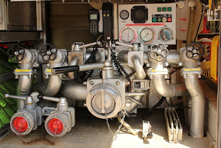
Suction and Delivery pipes
Flow (Ltr/Min) | Suction (mm) | Delivery (mm) |
450 | 50 | 50 |
900 | 75 | 50 |
1400 | 100 | 100 |
2280 | 150 | 150 |
2850 | 200 | 200 |
4540 | 250 | 200 |
Main Pump: There should be only one lower pressure limit for the main pump. Stopping of main pump should be only by manual push button which should be prominently indicated on the pump panel.
Diesel Pump: A pump of same capacity as fire pump, driven by a diesel engine or connected to any other alternate source of electric supply. The diesel pump should have a separate battery and panel with automatic auto manual change over and also interlocking device to be provided so that diesel pump and electric pump do not operate simultaneously.
Lower pressure limit switch should also be incorporated in the diesel pump to make the start automatically at pre-set drop in pressure.
Jockey Pump: A pump of small capacity, which is set to come into operation, automatically with drop in static pressure in the system and to automatically stop when the pre-set pressure is reached again.
There should be two pressure switches – one with upper and lower limit, for Jockey pump.
Terrace Pump: An electrically driven pump, located on the terrace connected to a terrace tank with gate valve on suction side and to the internal hydrant system with non-return valve on delivery side.
Risers: Internal hydrant form part of any of the following systems: –
1) Dry-Riser system: An arrangement of firefighting within the building by means of vertical rising mains not less than 100 mm internal diameter with landing valves on each floor/landing which is normally dry but is capable of being charged with water usually by pumping from fire service appliances.
Dry-Riser main system could be installed in building where the height of building is above 15 meters but not exceeding 24 meters up to terrace level. Dry-Riser system does not include hose reel, hose cabinets, fire hose and branch pipes.
The rising main should have two-day fire service inlet without non-return valve at ground level, in front of each such block. It should also be provided with an air-releasing valve at the top level and drain valve at the bottom. The inlet should be about 1 meter from the ground level, and easily accessible and unobstructed at all times.
2) Wet-Riser system: An arrangement for firefighting with the building by means of vertical rising mains of not less than 100 mm internal diameter with landing valves on each floor/landing for firefighting purposes and permanently charged with water from a pressurized supply.
The system should consist of a pipe or number of pipes depending on the area and height of the buildings permanently charged with water under pressure with landing valves, hose reel, hose, branch pipe, etc. at every floor level.
This system should have an automatic pump with pressure differential switch along with stand by pump during power failure. This system is continuously pressurized with water.
Fire service inlet with non-return valve along with gate should be provided and 2 numbers of 63 mm inlets for 100 mm and 4 numbers for 150 mm. Any point should be approachable within 30 meters.
Wet riser shall be interconnected at terrace level to form a ring and cut-off shall be provided for each connection to enable repair / maintenance without affecting rest of the system.
3) Wet-Riser cum Down-Comer system:
4) Down-Comer system: Single headed landing valve, connected to a 100 mm diameter pipe taken from the terrace pump delivery should be provided at each floor / landing. A hose reel is directly tapped from the down-comer pipe should also be provided on each floor / landing. The diameter of the hose reel shall not be less than 19 mm.
Siting & Protection
(a) Good siting and protection of all water supplies is essential. These should not be sited in inaccessible locations and should be protected from inadvertent hits from the vehicles etc.
(b) These should not be sited with their openings towards explosive stores houses etc.
(c) The fire appliances such as hoses & branches etc. should be available close to the hydrants.
(d) These should not obstruct movement of other emergency services like, fire engines, ambulances, etc.
Inspection and Maintenance

(a) These should be inspected, maintained and tested periodically.
(b) Information regarding the layout of hydrant points, other appliances availability etc. should be available for ready references.
(c) The names/lists of the contact persons should be displayed.
Training
(a) Adequate number of persons shall be trained in the maintenance and testing of water equipment installed.
(b) Training and retraining should be carried out to ensure competence of the personnel.
(c) A viable system for alerting and calling personnel necessary for the efficient operation of all water equipment during silent hours should be incorporated.
(d) Mock drills should be held at least twice a year.